Protect Your Energy Storage System
Field-Proven, UL 1973 Recognized
Field-Proven, UL 1973 Recognized
Nuvation Energy provides configurable battery management systems that are UL 1973 Recognized for Functional Safety. Designed for battery stacks that will be certified to UL 1973 and energy storage systems being certified to UL 9540, this industrial-grade BMS is used by energy storage system providers worldwide.
Reliable
- Nuvation Energy battery management systems are high-reliability electrical controls that have been continuously improved upon for over a decade. The “G4” and “G5” designations of our High-Voltage BMS refer to fourth and fifth generation product iterations.
- Used in hundreds of energy storage systems worldwide and trusted by energy storage providers, our BMS is a mature field-proven product that has been safely managing large-scale energy storage platforms for many years.
- All our battery management systems have been third-party tested by UL (Underwriters Laboratories) and Recognized to the UL 1973 standard for Functional Safety. The Nuvation Energy BMS has been rigorously tested for its responsiveness to an exhaustive range of potential safety incidents and found by UL to manage them all in functionally safe manner. Our UL certifications can be verified on the UL website. The G5 BMS is also CE conformant and has been certified to the widely recognized IEC 60730-1 (Annex H) standard for automatic electrical controls.
Scalable
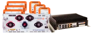
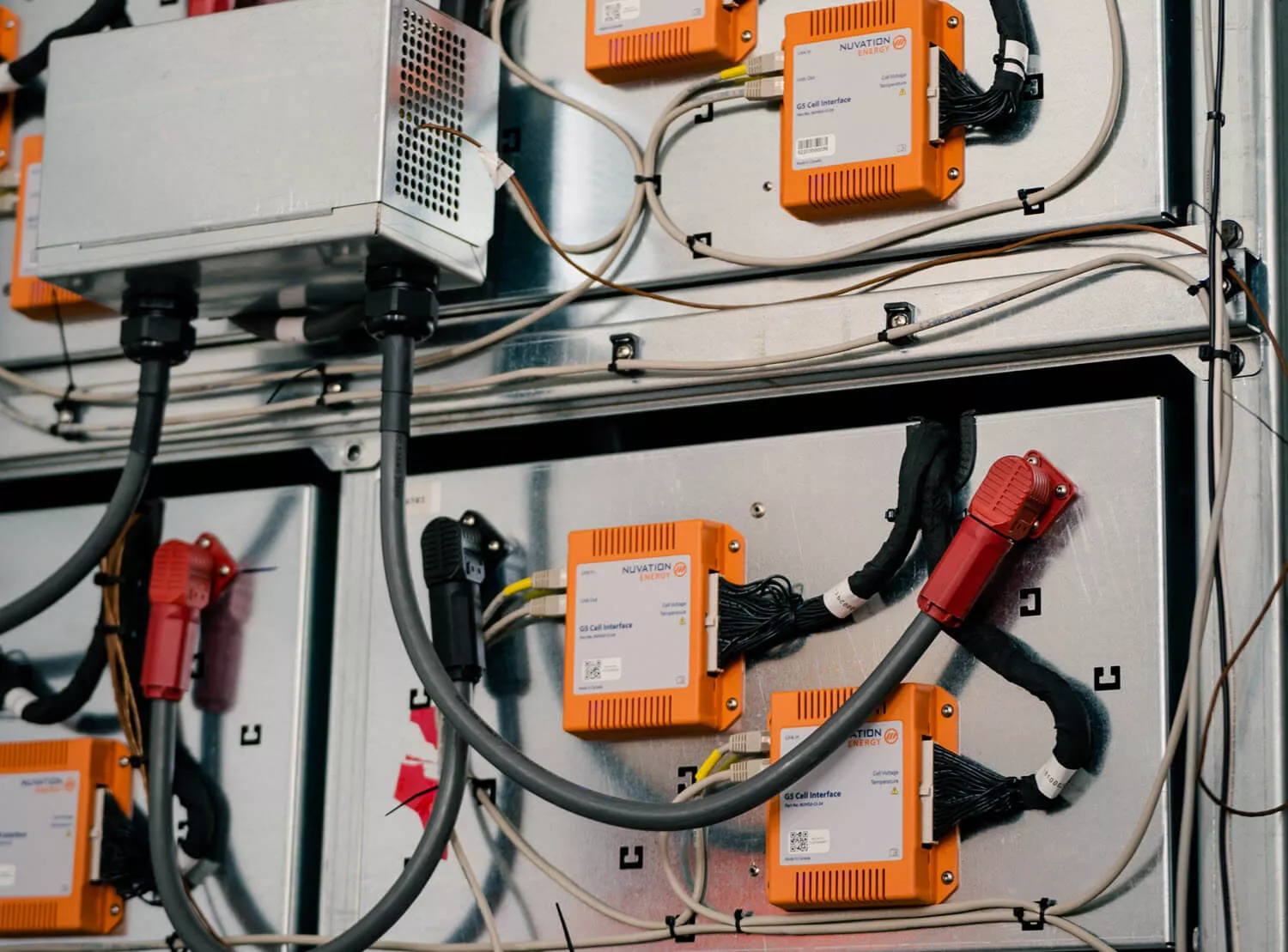
Nuvation Energy’s High-Voltage Battery Management Systems are designed to scale from managing a single battery stack up to 1500 V to managing 16 stacks in parallel with the Multi-Stack Controller. We will also provide UL certified cable harnesses to connect the BMS modules in each stack.
Powerful
The G5 High-Voltage BMS is the newest addition to the Nuvation Energy BMS family. Designed for lithium-based chemistries (1.6 V – 4.3 V cells), it supports battery stacks up to 1500 V and is available in 200, 300, and 350 A variants.
Flexible
Nuvation Energy’s battery management systems are highly configurable via a user-friendly Operator Interface. Outside of the factory-locked UL Recognized safety configuration, users can adjust many settings to meet specific application requirements. Examples include narrowing the State of Charge (SOC) / Depth of Discharge (DOD) range to preserve battery life or to increase cycle count, or expanding the warning triggers to support preventive maintenance, and adjusting battery management parameters within the functionally safe region to align with PCS requirements.
Intelligent
Nuvation Energy battery management systems include a range of intelligent features beyond cell balancing and managing battery safety thresholds. They include:
- Continuous Cell Balancing: The amount of time an ESS spends out of operation can be costly to the system operator. Traditional cell balancing takes place only at the top of the charge cycle which, depending on the amount of imbalance in the batteries, can result in a long out of service period for the ESS as it brings all the cells to a full charge. With Nuvation’s G5 BMS, cell imbalance is estimated when the fastest charging cell reaches 100% SOC, and the BMS balances the remaining cells during system operation. This enables the ESS to quickly resume operation. In many use-case scenarios Nuvation Energy’s continuous balancing approach delivered over 99% ESS uptime.
- Self-Diagnostics: On initial startup the BMS will run a self-test to ensure that data is propagating properly across all the BMS modules. This helps system installers find damaged, loose, disconnected, and incorrectly torqued sense wires.
- Stack Assembly Diagnostics: Improperly installed high-current connections in a battery stack can manifest as an increase in the internal temperature of the BMS. Temperature sensors inside the BMS will trip a warning notification when this occurs.
- Built-In Fan Controls: The BMS will detect temperature increases inside battery modules and turn on cooling fans (both AC and DC fans are supported) before these temperature rises are detected by ESS environmental controls.
- Contactor Life Tracking: While contactors are designed to be able to be opened under load, their usable life will be consumed if this occurs too often. The Nuvation Energy BMS records high-current occurrences of contactor opening and decrements the remaining life at each occurrence, based on contactor safety testing performed at UL laboratories for Nuvation Energy. The BMS will warn users as the contactors approach their end of life. It will also prevent further usage of the Stack Switchgear unit when the contactor life is fully consumed and is no longer safe to operate.
- Dynamic Current Limits: The battery management system provides the PCS with the maximum current threshold of the battery. The Nuvation Energy BMS will reduce these thresholds during charging and discharging to prevent over-temperature, over-charging, and over-discharging.
- Control Loop Tuning: A common issue that can arise between a BMS and PCS involves current and voltage oscillation brought about by the BMS changing current thresholds in response to the application of current from the PCS, and the PCS changing current levels in response to new threshold data from the BMS. This “control loop” problem is often managed on site during ESS commissioning by a complex process of implementing filtering in a controller that sits between the batteries and PCS. With Nuvation Energy’s BMS, this power oscillation can be quickly resolved via a few BMS settings.
Easy to Use
Unlike many other battery management systems, the Nuvation Energy BMS has been designed to provide an excellent user experience in addition to managing battery safety. A user-friendly Operator Interface can be accessed via PC through a direct connection to the BMS hardware or remotely. Battery status as well as configurable settings are viewable on a PC via most popular Internet browsers. A user can view a wide array of battery status data, or with secure access can change settings, upload a new configuration file, modify warning triggers, and even update the BMS firmware.
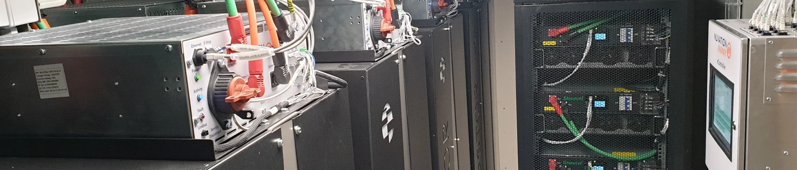
High-Voltage BMS
Configurable UL 1973 Recognized battery management systems for stationary and mobile energy storage applications.

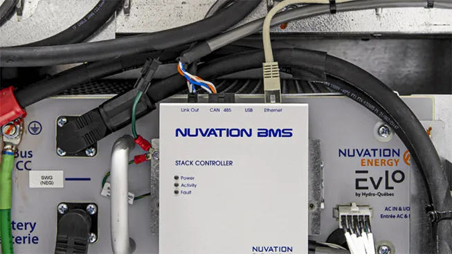
Multi-Stack Controller
Aggregates parallel battery stacks within your energy storage system, managing them as a single unified battery.

UL 1973 Recognized
Solutions for demand charge management and DER asset prioritization. Energy storage system design services.

Designed & Manufactured in USA & Canada
Nuvation Energy designs and manufactures all products in the U.S. and Canada, providing trusted, field-proven solutions for energy storage projects worldwide.

BMS Design Services
Custom-engineered battery management system solutions for unique applications and specialized requirements.